 04-04-2011, 11:52 PM
|
#1 |
|
Intake
Join Date: Oct 2008
Location: Michigan
Posts: 42
 |
ivce got an 89 supra with a 7mgte motor. the wires on my cam position sensor decided to break a new cps. well they are around $150 so im gonna try and rewire the whole thing but with being an 89 and having been soaked with oil i cant tell which colors are which. i chopped apart the rubber grommet where the wires go into the cps housing and found a red and a green wire so i have those 2. but i have no idea what the other colors are, they all look brown. i think they are supposed to be white and yellow but my question is this: which wires are what color under the cover. i plan on rewiring from the pick ups. does anyone have a picture of which wires are what colors and to which piuck up they go? 3 of the wires coming out of the housing come together but i can't tell what color they are. oh, and the previous owner cut around and took out the connector that attaches the wires from the cps to the harness so i don't have a connector or colors on the harness to match anything up to. i would really appreciate any help, thanks.
|

|

|
|
04-05-2011, 05:59 AM
|
#2 |
|
Bone Stock w Upgrades ;-)
Join Date: Apr 2010
Location: Tampa Bay
Posts: 228
|
This link could be helpful to you. The letter L = blue
http://www.cygnusx1.net/Supra/Librar...px?S=Main&P=48 |
|
|
|
|
04-05-2011, 04:04 PM
|
#3 |
|
Intake
Join Date: Oct 2008
Location: Michigan
Posts: 42
|
ive got that wiring diagram but that doesnt help me. here is a pic of my cam sensor. as you can see, you cant see what color any of the wires are. i need to find out what colors they used to be so i can rewire them to a new connector.
|
|
|
|
|
04-05-2011, 06:22 PM
|
#4 |
|
Bone Stock w Upgrades ;-)
Join Date: Apr 2010
Location: Tampa Bay
Posts: 228
|
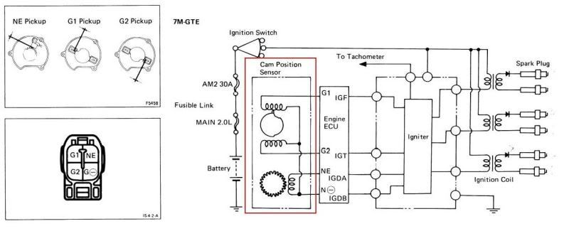
The 3 wires clipped together that are black are the ground (G-) for the three pickups. Looking at the open face of the cam position sensor its shaped roughly like the letter D. Going clockwise starting at the 12 o'clock position the sensors are:G1 (red and black wires), NE (blue and black wires), G2 (yellow and black wires). You may want to check each pickup with a Ohm meter before going to any trouble to make sure they are within specification and not shorted or open. The specification is 140-180 Ohms for each pickup. The air gap between the pickups and the rotating tip is 0.008 - 0.016" (8 -16 thousandths of an inch). You'll need a feeler gauge to check it. If it checks out okay you'll need to interface it with the wiring harness and you said that you had no plug. Most auto stores including NAPA have the push connections that you can use. Here's a photo from the manual. You'll have to decide where to hack into the wiring where it's not rotten or cracked. If you cut anything inside the cam position sensor housing, slide off the woven insulation first to try and reuse it. Cut the wires staggered so that the soldered repairs don't lay next to each other to avoid shorting. Use silicone seal or heat shrink tubing to insulate. Slide the woven insulation back over before crimping on the push connection. Another thing to be aware of is that the oil seal in these can fail and that's a messy repair. During the time mine was leaking I put an aluminum foil "cup" under it to catch the drips. Good Luck.
Last edited by Bru; 04-05-2011 at 06:34 PM. |
|
|
|
|
04-05-2011, 07:46 PM
|
#6 |
|
Intake
Join Date: Oct 2008
Location: Michigan
Posts: 42
|
all that info will definitley help. thanks!
|
|
|
|
|
04-06-2011, 03:51 AM
|
#7 | |
|
Supra Forum Moderator
Join Date: Nov 2009
Location: Green-Ohio
Posts: 1,297
|
Quote:
and C is for Cookie num num num! 
__________________
 92 Ma71 7mGTE Auto. SafcII Supra FAQ Supra MKIII FAQ Classified Section guidelines : |
|
|
|
|
|
04-06-2011, 04:04 PM
|
#8 |
|
Intake
Join Date: Oct 2008
Location: Michigan
Posts: 42
|
so i took a closer look digging into it and found that when i took off black wraps that go around the wiring that i do have what looks like a red wire to going to one and a green going to another. i assume the green one would be blue. the problem is that i can't decipher either wire on g1, g2 has the green/blue wire and the NE has the red wire. that doesn't match up with what colors you said they should be :S from that diagrahm did you just figure out which pickup went to which location in the connector and crossed that with which color wire went where in the connector? i think i should probably rewire it with the colors that are on it but usually when people replay to posts they know what they are talking about. i just dont want to do it and it be wrong and have to redo it.
|
|
|
|
|
04-06-2011, 07:27 PM
|
#9 |
|
Supra Forum Moderator
Join Date: Nov 2009
Location: Green-Ohio
Posts: 1,297
|
Youd be suprised to learn that people actually do post miss information intentionally. That page is a direct link to a creditable if not worshiped site.
You are right tho, the information you posted does not go hand in hand with the links data. I don't see what the problem is tho? just fallow the pins and hard solder them when your done. oh and take a more in focus picture. I really want to see what those wires look like.\ here give this a gander http://www.cygnusx1.net/Supra/Librar....aspx?S=D&P=34
__________________
92 Ma71 7mGTE Auto. SafcII Supra FAQ Supra MKIII FAQ Classified Section guidelines : Last edited by Green7mgte; 04-06-2011 at 07:31 PM. |
|
|
|
 |
|
|
 Similar Threads
|
||||
| Thread | Thread Starter | Forum | Replies | Last Post |
| setting cam position sensor? | mattromey | MKIII Supra | 8 | 11-19-2009 04:54 PM |
| Cam Position Sensor | JMoses | MKIII Supra | 4 | 08-19-2009 05:09 PM |
| can cam position sensor cause | 88Tsupra | MKIII Supra | 4 | 03-22-2007 01:25 AM |


 Linear Mode

